The Hydrodynamic Necessity of Precision Jetting Architectures
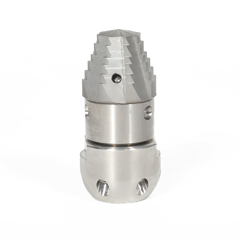
Deploying a high-efficiency pipe cleaning nozzle assembly provides municipal sewer teams, industrial facility engineers, and commercial plumbers with a highly focused, fluid-driven solution for cleaving through hardened mineral scales, structural root intrusions, and thick grease blockages. By converting raw high-pressure pump flow into directed, high-velocity fluid streams through precisely machined ceramic or carbide orifices, these tools create a self-propelling kinetic system. This configuration delivers an increase in impact striking energy of up to 400% compared to standard open-bore pipe wash extensions. This advanced engineering ensures full 360-degree wall scouring, keeps the nozzle moving forward through pipe runs exceeding 150 meters, and safely restores pipe carrying capacity without causing structural wall damage.
In modern fluid transport infrastructure, clearing clogged pipelines requires balancing strong forward-driving force with aggressive, sweeping clean action. Stubborn blockages like calcium scale deposits, solidified industrial greases, and fine root masses can quickly choke down pipeline diameters, leading to system backups. Standard mechanical drain snakes often just punch a narrow hole through these blockages rather than clearing them entirely, leaving behind a residue that triggers rapid re-clogging. Transitioning to custom-machined hydro-jetting nozzle heads resolves these maintenance vulnerabilities by focusing pressure directly against the pipe's interior walls. This structural setup leverages the fluid's own velocity to slice away deposits and wash out debris in a single pass.
Fluid Mechanics and Orifice Metallurgy Profiling
The cutting power and service life of a jetting tool depend directly on the design of its internal fluid chambers and the hardness of the material used to line its spray orifices. Poor material choices can lead to rapid internal wear and pressure drops.
Industrial Ceramic Orifice Insert Longevity
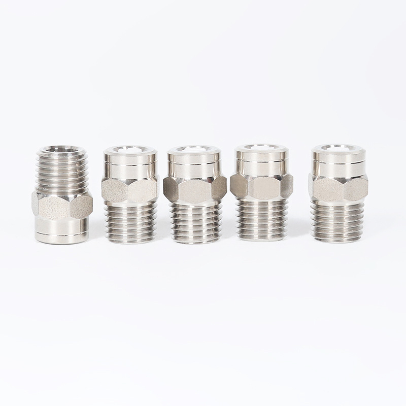
High-performance jetting tools utilize inserts machined from crystalline ceramic compounds. These inserts feature an incredibly smooth internal surface that minimizes fluid friction, allowing the water stream to stay tightly focused over longer distances. With a hardness rating that easily resists abrasive wear from particulate matter in recycled water systems, ceramic orifices maintain their precise spray patterns for up to 250 operating hours under continuous pressures reaching 300 bar.
Hardened Stainless Steel and Carbide Inserts
For high-pressure applications operating up to 1,000 bar, nozzles are fitted with tungsten carbide or hardened stainless steel orifices. While stainless steel inserts are more cost-effective and handle high physical impacts well, their softer material profile makes them vulnerable to erosion from fine sand or grit suspended in the jetting water, which can widen the orifice and cause a pressure drop after about 40 to 60 hours of use.
Comparative Design Evaluation: Static Penetrator Nozzles vs. Controlled Rotational Nozzles
Selecting the optimal pipe cleaning tool requires evaluating forward pulling power against circumferential wall coverage, water consumption rates, and maintenance demands. The comparative table below details the performance boundaries between static and rotating nozzle systems.
Table 1: Technical Fluid Mechanics and Material Removal Performance Matrix of Primary Pipe Jetting Configurations
| Fluid Dynamic Factor Profile |
Static Fixed Penetrator Nozzle |
Fluid-Driven Controlled Rotational Nozzle |
| Forward Traction Thrust Profile |
Maximum (Rear Jets Optimized at 15° - 25° Angles) |
Moderate (Energy Split to Power Rotational Head) |
| Pipe Wall Cleaning Coverage |
Linear Striations (Leaves uncleaned gaps between streams) |
Continuous 360° (Complete Spiral Scouring Pattern) |
| Mineral Scale Cleaving Capacity |
Moderate (Relies purely on forward impact) |
Exceptional (Rotational speed maximizes shearing forces) |
| Internal Fluid Turndown Range |
Infinite (No moving components to jam) |
Restricted (Requires a minimum flow rate to spin) |
| Primary Application Target |
Initial Punch-Through of Total Line Blockages |
FOG (Fat, Oil, Grease) Removal and Polishing Ends |
This fluid comparison highlights a clear operational division. Static penetrator nozzles excel at long-distance pulling and breaking through total line blockages because their rear jets are angled sharply backwards to maximize forward thrust. However, because their spray patterns are fixed, they leave behind thin lines of uncleaned debris along the pipe walls. Controlled rotational nozzles bridge this cleaning gap by using internal viscous governors to spin the spray head at a steady speed, ensuring the water streams scour every square millimeter of the pipe interior to wipe out grease and root remnants completely.
Advanced Hydrodynamic Geometry and Thrust Angle Mechanical Control
Modern pipe jetting nozzles use optimized physical designs to boost pulling power and help operators navigate past sharp pipe bends and fittings.
- Dual-Angle Rear Thrust Arrays: The nozzle body features two rings of rear-facing jets. The inner ring is set to a tight 15-degree angle for maximum pulling power, while the outer ring is positioned at 30 degrees to flush dislodged debris back down the line.
- Front-Facing Point-Striking Cutters: Fitted with a sharp, forward-angled front jet, this port punches an opening through thick blockages ahead of the nozzle, clearing a path for the body to slip through.
- Viscous Governor Fluid Braking Assemblies: Inside rotating nozzles, a chamber filled with specialized silicone fluid controls the spinning speed. This brake prevents the head from spinning too fast at high pressures, keeping the water streams concentrated to slice through tough root masses cleanly.
Step-by-Step Flow Matching and Field Operation Protocol
Because mismatching a nozzle to a pump's output can cause pressure drops or strain the motor, field crews use a structured process to size and verify their equipment.
- Pump Flow Parameter Assessment: Read the digital system metrics on the jetting trailer to find the pump's exact output (e.g., finding a flow rate of 60 liters per minute at 150 bar).
- Orifice Calculation and Sizing: Use an industry flow chart to size the nozzle inserts. The total area of the open orifices must match the pump's output; sizing them too small can over-pressurize the pump, while sizing them too large drops the water velocity.
- Inserting and Torquing the Ports: Thread the selected ceramic or steel inserts into the nozzle body using a calibrated torque wrench, ensuring they are snug to prevent high-pressure water leaks.
- Securing the Hose Line Safety Connection: Thread the nozzle assembly onto the high-pressure hose line and tighten it securely. Slide a flexible steel safety leader hose onto the end to keep the nozzle from turning around and traveling backward toward the operator.
- Lowering and Pressure Activation: Insert the nozzle head manually at least 1 meter into the pipe opening before throttling up the pump. Slowly ramp up the pressure to engage the rear jets, allowing the tool to pull itself smoothly up the pipe run.
Mitigating Water Hammer Stress Profiles and Managing Internal Cavitation
While professional jetting nozzles are engineered to handle intense fluid forces, abrupt pressure spikes and water aeration can cause rapid internal material fatigue.
Preventing Kinetic Water Hammer Structural Cracks
Water hammer occurs when high-pressure water flow is shut off instantly by a control valve, sending a violent shockwave back down the line to the nozzle head. This pressure spike can crack brittle ceramic inserts and deform internal threads. To protect the assembly, operators should use smooth, slow-closing bypass valves and avoid sudden throttle drops, allowing the intense fluid energy to bleed off safely.
Controlling Micro-Cavitation Material Pitting
Internal cavitation happens when sharp turns inside the nozzle's fluid channels cause localized pressure drops, forming tiny vapor bubbles. When these bubbles pass into the high-pressure spray zones, they collapse violently, creating micro-explosions that can pit steel walls over time. Field crews can control this internal erosion by flushing their water systems to remove trapped air and using rounded fluid chambers that maintain smooth, steady water movement through the tool.



 中文简体
中文简体