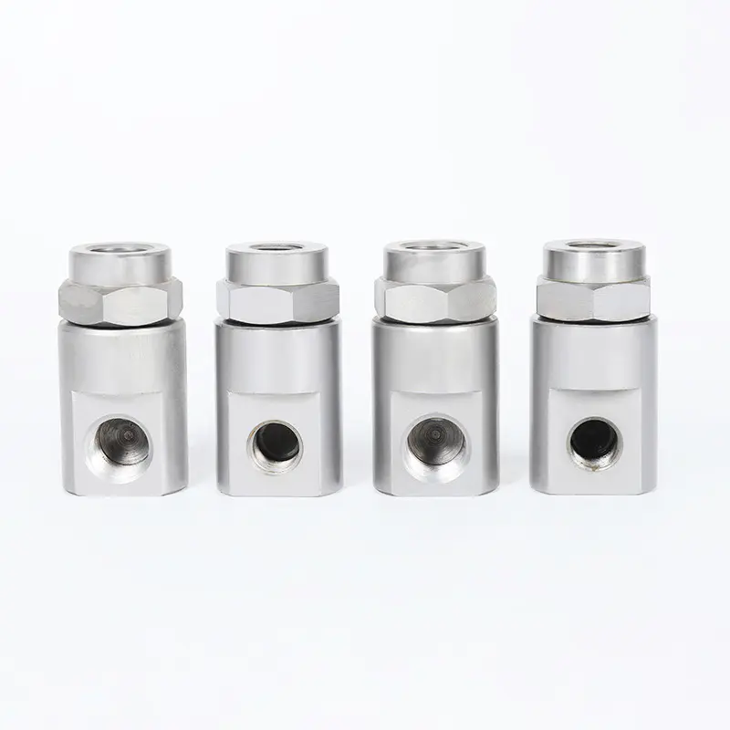
Maintaining the operational integrity and pressure retention of industrial fluid cleaning networks depends entirely on the selection, fitment, and material composition of the underlying coupling system. A high-grade pressure washer connector serves as the critical structural link between high-displacement pumps, heavy-duty hoses, trigger guns, and spray nozzles. By bridging these components, the connector transforms a series of isolated fluid paths into a single unified system capable of containing extreme hydrostatic forces, preventing system leaks, and mitigating high-frequency pressure spikes that would otherwise damage delicate pump manifolds.
Dimensional Engineering and Structural Thread Profiles
The fundamental design constraint of any pressure washer connector is its mechanical thread geometry. High-pressure water lines cannot rely on generic friction fittings; instead, they demand precise machined thread specifications that mechanically lock the male plug and female socket surfaces together against axial separation forces.
The commercial and industrial power cleaning industry divides these threaded adapters into distinct dimensional categories based on geographic origin, nominal diameter, and localized sealing types. Selecting the incorrect thread configuration will cause immediate thread galling or produce a loose joint that can blow apart under full system pressure.
M22 Thread Configurations: 14mm vs. 15mm Internal Pin Dynamics
The most common threaded connection type used to join hoses directly to pump outlets is the M22 metric design. However, this configuration contains a subtle internal variance that represents a common point of mechanical failure in the field:
- 14mm Internal Stem Profile: Features a central male core pin measuring exactly 14.0 mm in outer diameter. This is the heavy-duty commercial industry benchmark, optimized for a tight, high-pressure seal when combined with internal rubber O-rings.
- 15mm Internal Stem Profile: Utilizes an enlarged central pin measuring 15.0 mm across. This configuration is widely deployed on entry-level residential equipment. Forcing a 14mm female coupler onto a 15mm male stem will strip the threads, while installing a 15mm female coupler onto a 14mm stem creates a 1.0 mm structural air gap that causes immediate, high-volume fluid spraying under pressure.
National Pipe Thread (NPT) Taper Mechanics
Unlike straight metric threads that use a rubber washer to stop water, National Pipe Thread (NPT) fittings feature a built-in 1-degree, 47-minute taper angle along the thread axis. As an NPT male connector is driven into a matching female port, the sloping thread profiles wedge tightly together, forming a continuous metal-to-metal seal. This tapered engagement requires the use of polytetrafluoroethylene (PTFE) thread tape or liquid pipe dope to lubricate the threads during assembly, preventing binding and filling micro-gaps to guarantee a watertight seal.
Kinematic Quick-Disconnect Ball-Lock Assemblies
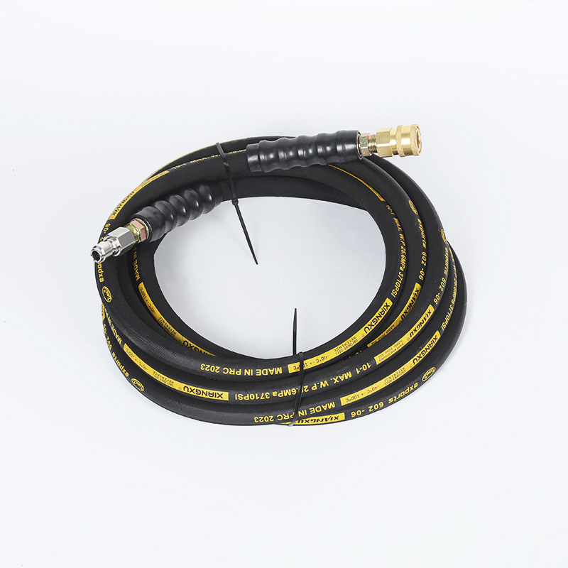
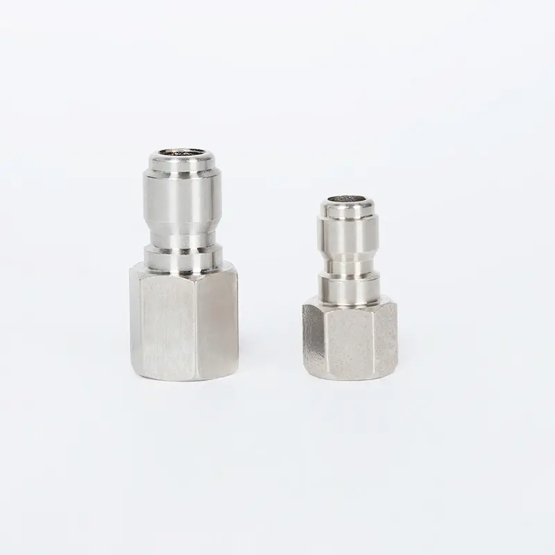
To speed up field setups and accessory swaps, commercial operators often upgrade threaded connections to quick-disconnect (QD) coupling systems. These systems use a snap-lock design that lets technicians connect or disconnect lines in seconds without using wrenches.
The internal mechanics of a high-pressure female quick-disconnect coupler rely on a ring of hardened stainless steel locking bearings—typically containing 6 to 8 detent balls distributed evenly around the internal circumference. When the spring-loaded outer sleeve is pulled back, the locking balls can move outward into an internal groove. This allows the hardened male plug to slide completely into the socket barrel. Releasing the sleeve forces the bearings back inward, locking them into a matching groove on the male plug to securely anchor the connection.
Quick-Connect Sizing Tiers: 1/4-Inch vs. 3/8-Inch Standards
Quick-disconnect components are split into two primary industrial sizes based on their location and fluid flow requirements within the system layout:
- 3/8-Inch Quick Connects: Installed at high-volume junctions, such as pump-to-hose and hose-to-gun connections. This larger internal diameter minimizes friction losses, allowing high water volumes to pass without dropping pressure.
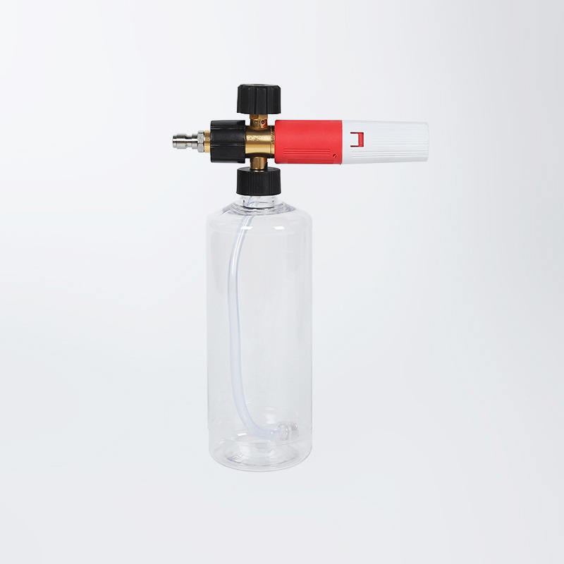
- 1/4-Inch Quick Connects: Positioned at the end of the spray wand to handle quick changes between colored spray nozzles, foam cannons, and surface cleaners. Their lightweight design makes handling the wand less tiring while keeping the nozzle locked straight.
Metallurgical Material Limits and Structural Parameters
The metal used to manufacture a pressure washer connector directly determines its maximum safe pressure rating, corrosion resistance, and total operational lifespan. A connector made from a low-grade metal alloy will deform over time under the constant vibrations of a gas or diesel engine pump.
The table below provides a detailed mechanical performance breakdown of the three primary metal alloys used to build industrial-grade pressure washing connectors:
| Connector Alloy Composition |
Maximum Safe Operating Pressure |
Ultimate Tensile Yield Strength |
Chemical Corrosion Resistance |
Primary Operational Setting |
| Machined T-304 Stainless Steel |
5,000 to 6,500 PSI |
Approx. 515 MPa |
Excellent (Resists harsh acids, bleaches, and salts) |
Continuous industrial use, food processing, contract washing |
| Extruded HPb59-1 Forged Brass |
3,000 to 4,000 PSI |
Approx. 380 MPa |
Moderate (Prone to oxidation from corrosive chemicals) |
Standard commercial cleanups, property maintenance |
| Anodized 6061-T6 Aluminum |
1,500 to 2,500 PSI |
Approx. 276 MPa |
Low-Moderate (Protected by anodized coating layer) |
Lightweight consumer units, intermittent jobs |
Table 1: Metallurgical performance metrics, maximum safe pressure thresholds, and environmental suitability boundaries for pressure washing couplers determined under standard hydro-mechanical laboratory stress testing.
Elastomeric Sealing Engineering and O-Ring Compound Physics
While the outer metal housing provides the mechanical strength to keep components connected, the actual water seal is maintained by a small, flexible ring hidden inside the assembly called an O-ring. As water pressure rises, it forces the O-ring into the sealing gap, blocking fluid leaks.
Standard pressure fittings typically come with affordable Nitrile (Buna-N) O-rings, which offer reliable service for cold-water cleaning jobs up to 60°C. However, when a job requires a hot-water burner to melt through grease and oil, standard nitrile seals can quickly harden, crack, and fail. Under these extreme conditions, engineers upgrade the seals to Fluoropolymer (Viton) O-rings. Viton seals retain their flexibility and shape at continuous temperatures up to 200°C (392°F) and resist degradation when exposed to aggressive cleaning chemicals like sodium hypochlorite (bleach) and heavy degreasers.
Preventing O-Ring Extrusion Failures
When water pressure spikes beyond a connector's design limits, a flexible O-ring can be forced into the tiny space between the male plug and female barrel. This pressure exposure cuts and shreds the ring material, causing a sudden loss of pressure. Using matching hard plastic backup rings next to the rubber O-ring reinforces the seal, preventing extrusion damage and extending connector life under high-pressure conditions.
Installation Engineering, Torque Logistics, and Field Fitting Sequences
Properly assembling a high-pressure connector network requires following precise mechanical steps. Poor assembly techniques, like cross-threading or over-tightening joints, can weaken metal structures and lead to failures during operation.
- Inspect Threads and Sealing Grooves: Examine all connector threads for nicks, burrs, or dirt before assembly. Check the inside of female quick-disconnect barrels to ensure the internal O-ring sits flat in its retention groove without twists or tears.
- Apply Thread Sealant Layering (For NPT Connections Only): Wrap premium high-density PTFE thread tape around the male NPT threads in a clockwise direction, following the path of the threads. Apply exactly 3 to 4 complete wraps of tape, leaving the first thread bare to prevent tape shreds from breaking off into the water line and clogging the spray nozzle.
- Execute Parallel Wrench Tightening: Hand-thread the connectors together to ensure clean engagement. Next, use two open-ended wrenches: use one wrench to hold the base body steady and prevent it from twisting, and use the second wrench to tighten the compression nut until it seats firmly against the shoulder line.
- Lubricate Ball-Lock Slides: Apply a few drops of synthetic silicone lubricant to the stainless steel locking balls and outer sliding sleeve. Regular lubrication ensures smooth snap-lock operation and prevents the bearings from jamming when exposed to dirt and overspray on the job site.
- Perform a Low-Pressure Air Purge Test: Connect the water source but keep the pressure washer engine turned off. Squeeze the trigger gun to pass low-pressure water through the lines, purging out trapped air pockets. Eliminating air prevents destructive cavitation hammering forces when the high-pressure pump is started.
Troubleshooting Field Connection Leakage and System Failures
When a pressure washing system struggles to reach its rated operating pressure, or if water continuously drips from the line junctions, the root cause can usually be traced to a specific worn component inside the connector assembly.
A common issue is a steady leak coming directly from a quick-disconnect junction. This problem typically occurs when fine sand or grit gets trapped inside the coupler barrel, scratching the polished face of the male plug or slicing the internal rubber O-ring. To fix this, the technician must pull back the sleeve, clear out the debris, and use an O-ring pick to replace the damaged seal with a fresh, lubricated Viton ring.
Another problem is a quick-connect sleeve that jams or refuses to snap forward into its locked position. This issue is often caused by mineral scale buildup or rust binding the internal springs, which can happen when equipment is stored damp after working with hard water. To restore smooth operation, soak the uncoupled fitting in a mild commercial descaling solution to dissolve the mineral crust, dry the component completely, and coat the spring assembly with a high-performance marine grade anti-seize spray to protect the mechanism from future corrosion.



 中文简体
中文简体